Saturn Quake
May 3, 2015 at 2:35 pm (CST)
3 comments
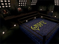 Quake for the Sega Saturn is an interesting port. Actually, rather than really being a port at all, it's Quake completely reconstructed in the SlaveDriver engine, which is the engine also used by Lobotomy Software's console ports of PowerSlave and Duke Nukem 3D.
A few people have expressed interest in being able to recover and/or port the levels from this version of the game, so it's been sitting around on my list of games to take a look at for quite a few years now. I finally got around to taking a look at the LEV files a few weekends ago on a whim, and after a couple more weekends of chipping away at it, it's at a point where it's ready to be included in a Noesis release.
Support in Noesis is nice on its own and can facilitate porting the maps over to other engines (with a good bit of manual effort), but I also want to share all of my findings so far, mostly for the sake of posterity. There's enough information here to start out on a crude level editor for the Saturn version itself (given that just moving planes around with respect to nodes seems to work out fine, but may require more documentation on the visibility data), but I'd probably be scared to meet the guy that decides to make that effort. Eventually, though, I'd overcome my fear, and maybe try to help him find a girlfriend.
Saturn Quake LEV File Format
-
1. Overview
2. Noesis Implementation
-
2.1. Exporting
-
3.1. Sky
3.2. Level Data
-
3.2.1. Header
3.2.2. Nodes
3.2.3. Planes and Geometry
3.2.4. Entities
3.4. Global Palette
3.5. Texture Data
3.6. Table Data 2
3.7. Embedded Resources
3.8. Visibility Data
1. Overview
-
First and foremost, remember that this document is incomplete, and a lot of it is still speculative. Feel free to contribute additional findings.
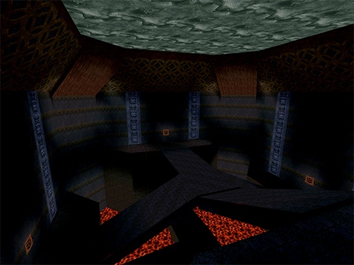
All atomic types should be read in big-endian format unless otherwise noted. Common notation is used for atomic types (int16, uint16, int32, uint32, etc.) and data structures are presented as C-style structs. Fixed-format normals are represented in the range of -16384..16384.
I haven't looked into how similar this incarnation of the format is to the SlaveDriver ports of PowerSlave and Duke Nukem 3D. It might be possible to adapt to one or both of them without too much effort.
Parsing through a given LEV file from top to bottom requires a good bit of knowledge of the format, as we aren't provided with any convenient offsets, and data sizes must often be derived from a count and the size of an explicit structure. See the File Segments section for more information.
2. Noesis Implementation
-
There are a few things to take note of about the Noesis implementation of this format.
Static light colors are mapped by fixed values in the 0..17 range, and by default, Noesis maps these values linearly to vertex colors in the 0..1 range. This allows users to easily remap the values as desired, and maintains compatibility with export targets that aren't aware of what subtractive vertex colors are. This means the default vertex colors and modulation you see aren't very faithful to what's seen in the game:
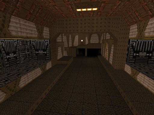
For this reason, the -qsatsubcolor command is provided. (you can put it in the preview command list under "Tools|Data viewer|Persistent settings|Other|Default preview commands" in order to make it the preview default) Using this command will use the original palette (which has a subtle bias against red) and enable subtractive vertex colors:
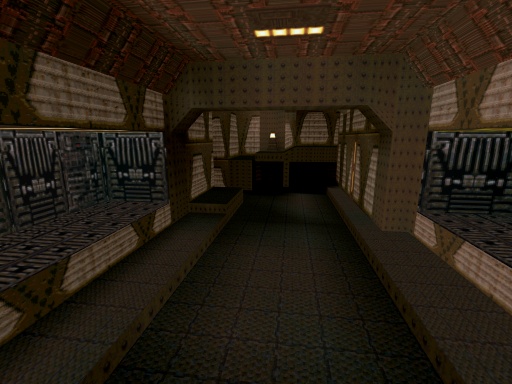
However, be aware that most export targets don't understand what subtractive vertex colors are, and what you see isn't what you'll get on the other side.
Another problem with this format is that the vectors used to place tiles are pretty low-precision, and will produce situations like this:
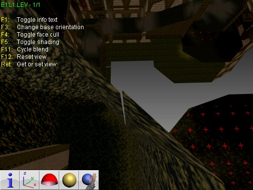
Noesis attempts to fix this using the -qsatwelddist option. (which defaults to enabled) This will generate a higher-precision plane from the plane vertices, then project the tiling vectors in high precision onto that plane. The tile vertices are then welded to edges and/or points from the plane vertices and other geometry within the plane, generally fixing the problem pretty well:
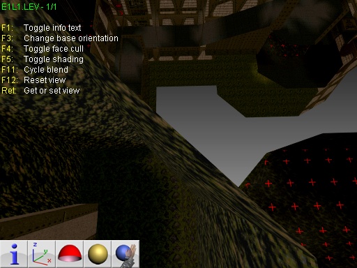
However, there are still gaps visible throughout the maps, due only to the fact that all vertices are provided in 16-bit fixed format, and parallel edges and other T-junction type situations aren't entirely uncommon. Doing a global vertex weld on points and edges can correct the remaining issues, but can also have undesired consequences, so take care in attempts at global welding. The default behavior of stitching up tiles with re-projected tile vectors is, on the other hand, pretty universally safe.
These levels also have lots of overlapping geometry. They rely on draw order and/or the Saturn's point-based sorting to do the right thing. Noesis checks for overlapping coplanar geometry by using the quantized polygon plane as a sort key, and when more than 1% of the surface area of a quad is overlapping another quad, it pushes the quad later in the draw list out by the distance specified with -qsatcoplofs. (the default is 0.1 units) Surface area percentage overlap is determined by taking the fraction of the remaining surface area of the candidate quad after clipping it against the other quad's edge half-planes. This approach is less-invasive than the alternative approach of slicing intersecting geometry, and is typically enough to resolve any potential depth fighting issues in your target renderer.
The last thing worth mentioning is that Noesis will generate visible geometry for the sky planes and apply the animated sky material to them. These planes aren't actually visible on Saturn hardware and are just used to assist in clipping/culling - sky is implemented on hardware using Scrolls. So if you'd rather not have this sky geometry be generated, -qsatnosky can be employed.
2.1. Exporting
-
When exporting Saturn Quake levels, it's worth considering the capabilities of your export format, and which one is most appropriate for the data you want to keep intact.
If you're aiming to get the content into a Quake engine, it's likely that you'll end up wanting to bake the vertex colors into a lightmap. I'm not aware of any existing path to do this with subtractive vertex colors, and some custom math and remapping would be necessary to bake out lightmap colors which are faithful to the subtractive vertex colors used by Saturn Quake.
Generating convex hulls from the plane geometry shouldn't actually be a big problem, but there may not be a tool path in existence that supports it, depending on what your engine target is. You can otherwise get away with just using the raw triangles for collision if the engine supports it.
Tying entities to applicable mover planes and identifying other entity types is the other task that would help with automating the porting process. It would be pretty trivial to spit out entities from the original Saturn levels, as well as using the entity data for movers to drive the appropriate plane geometry, but the work of charting out the entity types and their corresponding data needs to be done first.
3. File Segments
-
The segments in the file are laid out in this order (see detailed information for each section in order to determine actual sizes):
- Sky - The file begins with Sky data, which includes 32 bytes of palette, followed by exactly, and reliably, 131072 bytes of sky image data.
- Level Data - Immediately following Sky is a 60 byte header preceding the rest of the Level Data segment. The sizes in the header must be used to determine the offsets to geometry, entity, etc. data within the segment, and must be summed up to find the total size in order to reach the next segment in the file.
- Table Data 1 - This data may have something to do with the unverified poly-object link data inside of the Level Data segment. I haven't investigated this yet.
- Global Palette - A global palette which is referenced by common sprites and other resources. It's always 1024 bytes long, but a size is provided in the binary.
- Texture Data - A list of all textures. (including animation frames)
- Table Data 2 - Another set of large data entries. Still mostly undocumented.
- Embedded Resources - Presumably data pertaining to other resources embedded in the level. Still mostly undocumented.
- Visibility Data - Might be visibility data, primarily for entity/object culling. Unverified. Still mostly undocumented.
After parsing through the visibility data, you should end up at EOF. Each of these segments is pushed directly up against the last one with no alignment padding. See each segment's section for details on how to determine the full size of that segment.
3.1. Sky
-
The Sky segment is always 131104 bytes, with 32 bytes of rgba5551 palette data and 131072 bytes of image data. There are 64 animation frames. Each frame is a 4x4 page segment of 2x2 character sets of 8x8 cells, at 4 bits per pixel. This makes sense in the context of the Saturn's Scroll Configuration Units. Each frame should untile to a 64x64 image:


This segment can be safely skipped without any concern for varying sizes.
3.2. Level Data
-
The Level Data segment is comprised of many different data chunks, and its total size must be determined from the values in the Header.
Level geometry is defined by planes, which reference sets of quads and tiles. Large quads are a problem on the Saturn for a number of reasons, particularly for sorting and clipping, where actually clipping the geometry of a texture-mapped quad away will naturally squish the texture into the unclipped region of the quad. The other problem is that textures can't be tiled without rendering another quad for each repeated tile, which means you end up with a lot of geometry. This happens to work out pretty well for a game that aims to take on the role of lightmaps with nothing but per-vertex colors and Gouraud shading.
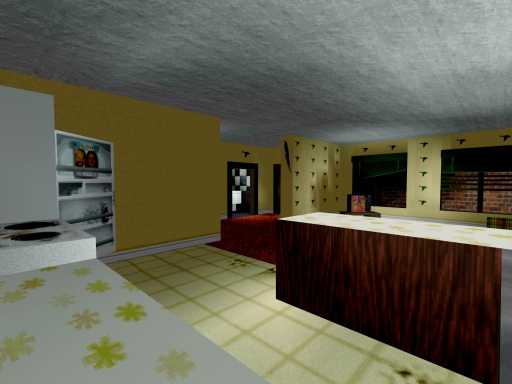
Saturn Quake provides per-vertex lighting index values for both explicit quads and tile sets. This is done as part of the vertex structure for explicit quads, and through the kLS_TileColorData stream for tile sets. The mapped lighting values are applied subtractively, and have a limited capacity for darkening brighter textures.
3.2.1. Header
-
The level data header is 60 bytes, and looks like this:
struct SLevHeader
{
	uint32		mUnknown1; //always 0?
	uint32		mUnknown2; //might represent a bank or collective size

	uint32		mNodeCount; //28 bytes each
	uint32		mPlaneCount; //40 bytes each
	uint32		mVertCount; //8 bytes each
	uint32		mQuadCount; //5 bytes each
	uint32		mTileTextureDataSize;
	uint32		mTileEntryCount; //44 bytes each
	uint32		mTileColorDataSize;
	uint32		mEntityCount; //4 bytes each
	uint32		mEntityDataSize;
	uint32		mEntityPolyLinkCount; //unverified - 18 bytes each
	uint32		mEntityPolyLinkData1Count; //2 bytes each
	uint32		mEntityPolyLinkData2Count; //4 bytes each
	uint32		mUnknownCount; //16 bytes each
};
Each of these counts/sizes must be used to determine the locations of subsequent pieces of data in the file, but the data isn't necessarily in the same order as the header entries. The following code demonstrates the order of the data in the file by setting an offset to each piece of data (all offsets are relative to the beginning of this segment):pInfo->mOffsets[kLS_Nodes] = sizeof(SLevHeader); pInfo->mOffsets[kLS_Planes] = pInfo->mOffsets[kLS_Nodes] + 28 * pInfo->mHdr.mNodeCount; pInfo->mOffsets[kLS_Tiles] = pInfo->mOffsets[kLS_Planes] + 40 * pInfo->mHdr.mPlaneCount; pInfo->mOffsets[kLS_Verts] = pInfo->mOffsets[kLS_Tiles] + 44 * pInfo->mHdr.mTileEntryCount; pInfo->mOffsets[kLS_Quads] = pInfo->mOffsets[kLS_Verts] + 8 * pInfo->mHdr.mVertCount; pInfo->mOffsets[kLS_Entities] = pInfo->mOffsets[kLS_Quads] + 5 * pInfo->mHdr.mQuadCount; pInfo->mOffsets[kLS_EntityPolyLinks] = pInfo->mOffsets[kLS_Entities] + 4 * pInfo->mHdr.mEntityCount; pInfo->mOffsets[kLS_EntityPolyLinkData1] = pInfo->mOffsets[kLS_EntityPolyLinks] + 18 * pInfo->mHdr.mEntityPolyLinkCount; pInfo->mOffsets[kLS_EntityPolyLinkData2] = pInfo->mOffsets[kLS_EntityPolyLinkData1] + 4 * pInfo->mHdr.mEntityPolyLinkData2Count; pInfo->mOffsets[kLS_EntityData] = pInfo->mOffsets[kLS_EntityPolyLinkData2] + 2 * pInfo->mHdr.mEntityPolyLinkData1Count; pInfo->mOffsets[kLS_TileTextureData] = pInfo->mOffsets[kLS_EntityData] + pInfo->mHdr.mEntityDataSize; pInfo->mOffsets[kLS_TileColorData] = pInfo->mOffsets[kLS_TileTextureData] + pInfo->mHdr.mTileTextureDataSize; pInfo->mOffsets[kLS_Unknown] = pInfo->mOffsets[kLS_TileColorData] + pInfo->mHdr.mTileColorDataSize; pInfo->mOffsets[kLS_RemainingData] = pInfo->mOffsets[kLS_Unknown] + 128 * pInfo->mHdr.mUnknownCount;In this case, the kLS_RemainingData offset is the start of the next segment in the file, Table Data 1.
3.2.2. Nodes
-
Node structures reference a range of planes, and some other not-well-documented stuff. They look like this:
struct SLevNode
{
	int16		mResv[2]; //always 0
	int16		mPos[3];
	int16		mDistance; //unverified, could be some kind of angle or axis offset
	uint16		mFirstPlane;
	uint16		mLastPlane;
	int16		mUnknown[6];
};
mUnknown seems to also contain some string references, which are used for message triggers. I haven't spent much time looking at these so far, but they do seem to cover the entire range of visible planes. The runtime doesn't actually seem to care for the purposes of rendering and culling if most of the structure is zeroed out, including the position and "distance", although I suspect it may cause issues with poly-objects.3.2.3. Planes and Geometry
-
Geometry is comprised of 4 basic structures: Planes, Quads, Tiles, and Vertices. Planes reference quads and tiles by index, in their respective kLS_Quads and kLS_Tiles lists. All vertex indices are direct indices into the kLS_Verts list. The offsets to each of these lists are specified in the Header section.
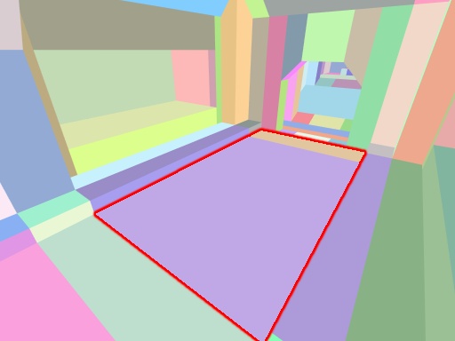
This image illustrates the separation of tiles and quads through color in the starting room of E1L1, where a single floor plane is outlined in red:
The Saturn has no notion of UV mapping, so that means UV coordinates for all of our geometry are implicit (although we do have some flags to flip them), with UV space (0,0) being at vert0, (1,0) at vert1, (1,1) at vert2, and (0,1) at vert3. It's possible to manipulate height/address/etc. over an existing texture in vram in order to effectively clip textures within tiles, but for whatever reason Saturn Quake doesn't do this, and we have lots of squished textures on quads to show for it. It seems lighting is often employed as a means of covering those situations up a little bit.
Plane structures from the kLS_Planes list look like this:
struct SLevPlane
{
	uint16		mVertIndices[4]; //vertices defining the plane
	uint16		mNodeIndex; //or 0xFFFF, used for triggers/links from planes
	uint16		mFlags; //typically 256, used largely for poly-objects like movers
	uint16		mCollisionFlags; //haven't mapped these out
	uint16		mTileIndex; //0xFFFF if no tile data present
	uint16		mUnknownIndex; //seems rarely used (usually 0xFFFF)
	uint16		mQuadStartIndex; //> end index if N/A
	uint16		mQuadEndIndex;
	uint16		mVertStartIndex; //first vert referenced by quads
	uint16		mVertEndIndex;
	int16		mPlane[4]; //fixed-format normal and distance
	int16		mAngle; //seems to be an angle about some axis
	uint16		mResv[2]; //always 0
};
Individual quads should be rendered for the plane starting at mQuadStartIndex and ending at mQuadEndIndex, with mQuadEndIndex being included in the list of quads rendered. Those values are indices into the kLS_Quads list. Entries in the kLS_Quads list are all 5 bytes (unpadded/unaligned), and they look like this:
struct SLevQuad
{
	uint8		mIndices[4];
	uint8		mTextureIndex;
};
mIndices are vertex indices but must be added to the plane's mVertStartIndex value in order to calculate the index into the kLS_Verts list. This is the case for all quads in the plane, and the base vertex index does not need to be adjusted per-quad. mTextureIndex is a direct index into the texture list, see the Texture Data section.For quad geometry, per-vertex colors (in the range of 0..17) are provided in the vertex position W's, where the vertex structure looks like this:
struct SLevVertex
{
	int16		mPosition[3];
	uint16		mColorValue; //the color index is in the high 8 bits
};
All vertex color indices map into a table that looks like this:
static const int32 skNativeSignedColorOffsets[18][3] =
{
	{-16,-16,-16}, {-16,-15,-15}, {-15,-14,-14},
	{-14,-13,-13}, {-13,-12,-12}, {-12,-11,-11},
	{-11,-10,-10}, {-10,-9,-9},   {-9,-8,-8},
	{-8,-7,-7},    {-7,-6,-6},    {-6,-5,-5},
	{-5,-4,-4},    {-4,-3,-3},    {-3,-2,-2},
	{-2,-1,-1},    {-1,0,0},      {0,0,0}
};
As applied to rgb555 values. This means that if we have a pure white rgb555 value of (31,31,31), the darkest it can be made from vertex color contribution is (15,15,15). If the color minus the color offset would go below 0, it will be clamped. But it's actually possible for the dynamic/flicker lights to end up wrapping back up to 31, so they'll appear to flicker up to white instead of darken.Care should also be taken to render quad geometry as dual-plane and/or ensure that the winding matches the plane's normal, as quads may be rendered backwards as a way of flipping the texture.
Finally, if we have a valid mTileIndex (which we may have in conjunction with valid quad lists), we need to render tile data for the plane as well. Each entry in the kLS_Tiles list looks like this:
struct SLevTile
{
	uint16		mTextureDataOfs; //byte offset into kLS_TileTextureData
	uint8		mWidth;
	uint8		mHeight;
	uint16		mColorDataOfs; //byte offset into kLS_TileColorData
	int32		mTileHorzVec[3];
	int32		mTileVertVec[3];
	int32		mTileBaseVec[3];
	uint16		mUnknown;
};
The total tile count in the SLevTile set is mWidth * mHeight. For each tile in the set, the kLS_TileTextureData data stream provides an 8-bit flag, and an 8-bit texture index. As with the quads, the texture index is a direct index into the texture list. The texture flags contain 2 important bits. Bit 0x10 means that the texture is flipped horizontally, and bit 0x20 means it's flipped vertically. Both flags may be used together to flip both horizontally and vertically.For each unique point within the tiles, the kLS_TileColorData provides 8-bit color index values in range 0..17 the same as the colors provided for quads via vertex position W's. UniquePointsPerRow is 2 + (mWidth - 1), and UniquePointsPerColumn is 2 + (mHeight - 1), so the total number of unique points per set of tiles is UniquePointsPerRow * UniquePointsPerColumn.
The rest of the values provide vectors which I'll refer to as TileBase, TileHorzVec, and TileVertVec. The values are stored as fixed 16.16 in order to provide some extra precision, so divide each int32 value by 65536 when converting to float. To plot the tiles, we do something like this:
const uint8 *pTileTextureData = pBaseOfTileTextureData + mTextureDataOfs;
const uint8 *pTileColorData = pBaseOfTileColorData + mColorDataOfs;
for (int32 tileY = 0; tileY < mHeight; ++tileY)
{
	for (int32 tileX = 0; tileX < mWidth; ++tileX)
	{
		RichVec3 tileCorner0 = TileBase + TileVertVec * tileY + TileHorzVec * tileX;
		RichVec3 tileCorner1 = tileCorner0 + TileHorzVec;
		RichVec3 tileCorner2 = tileCorner0 + TileHorzVec + TileVertVec;
		RichVec3 tileCorner3 = tileCorner0 + TileVertVec;

		const int32 tileIndex = tileY * mWidth + tileX;
		const int32 texFlags = *(pTileTextureData + tileIndex * 2);
		const int32 texIndex = *(pTileTextureData + tileIndex * 2 + 1);

		if (texFlags & 0x20)
		{
			//...flip texture vertically
		}
		if (texFlags & 0x10)
		{
			//...flip texture horizontally
		}

		const uint8 *pTopLeftData = pTileColorData + tileY * UniquePointsPerRow + tileX;
		TileVertColors[0] = pTopLeftData[0];
		TileVertColors[1] = pTopLeftData[1];
		TileVertColors[2] = pTopLeftData[1 + UniquePointsPerRow];
		TileVertColors[3] = pTopLeftData[0 + UniquePointsPerRow];

		TileVertPositions[0] = tileCorner0;
		TileVertPositions[1] = tileCorner1;
		TileVertPositions[2] = tileCorner2;
		TileVertPositions[3] = tileCorner3;

		//...take TileVertColors, TileVertPositions, the UV coordinates you generated using texFlags, and texIndex to render your quad
	}
}
The combined process of rendering the individual quads and the tiles is what ends up producing all visible geometry.3.2.4. Entities
-
Entities are located at the kLS_Entities offset specified in the Header section, and are 4 bytes each:
struct SLevEntity
{
	uint16		mType;
	uint16		mDataOfs;
};
mDataOfs is a direct byte offset into the kLS_EntityData chunk. The size of the entity data depends directly on the type. I've not yet spent any time mapping these things out, and the only one I've verified is the mover, which is type 0x92 and has an entity data size of 42 bytes.All changing and colored (beyond the natural blue/green hue of the default lighting offsets) lights are entities as well, and no concept of "lightstyles" for the baked lighting seems to exist.
3.3. Table Data 1
-
I haven't looked into what this segment is used for, but it requires some special handling to parse through. With stream set at the beginning of this segment, you can do something like this:
const int32 size1 = stream.ReadInt32();
stream.SeekAhead(size1);
const int32 elementCount = stream.ReadInt32();
for (int32 elementIndex = 0; elementIndex < elementCount; ++elementIndex)
{
	const int32 dataSize = stream.ReadInt32();
	const int32 unknown1 = stream.ReadInt32();
	const int32 unknown2 = stream.ReadInt32();
	const int32 unknown3 = stream.ReadInt32();
	stream.SeekAhead(dataSize);
}
Once this loop finishes, you'll be at the end of this segment in the stream.
3.4. Global Palette
-
This segment houses the global palette, which is referenced by a variety of common resources, particularly sprites. The palette is in the format of rgba5551. The segment starts with a 32-bit int specifying the palette data size (1024), and is followed by that many bytes of palette data. As the palette size is always 1024, the size of this segment is always 1028 bytes in total.
3.5. Texture Data
-
The texture data segment starts off with a 32-bit int, and is followed by a series of 64x64 at 4 bits per pixel images, each one having its own 16-color rgba5551 palette. Because every texture tile in this list is a fixed size, every entry is 2082 bytes and looks like this:
struct SLevTexture
{
	//these are unverified
	uint8		mFlags;
	uint8		mType; //always 130?

	uint16		mPalette[16];
	uint8		mImageData[2048];
};
These texture tiles are referenced by index directly in their presented order by the quad and tile data. The data itself is linear and can be decoded as you would any standard 4bpp palettized image.


All texture tiles are 64x64, which means there are plenty of segmented tile sets like this, rendered as four separate quads.
The end of the segment comes after the last image in the list.
3.6. Table Data 2
-
This segment is mostly undocumented. It starts out with 3084 bytes of data, and is followed by a series of data chunks. Each data chunk starts with an int16 (type?), and an int32 representing the size of the following data in bytes. The end of the segment is defined by the end of all data chunks.
3.7. Embedded Resources
-
This segment is mostly undocumented. The first int32 in the segment is the size of the first part of the segment following its 16-byte header. Other values in that header specify item counts for data in the first part of the segment. Skip ahead 16 + size from the beginning of the segment to reach the second part of the segment.
The second part of the segment contains embedded resource data. It begins with a 60-byte header, which is currently undocumented. The last int32 in that header (at offset 56) represents the size of the whole embedded resource block. Skip ahead by 60 + that size, from the beginning of the embedded resource header, to reach the end of the segment.
3.8. Visibility Data
-
This segment is mostly undocumented. It begins with an int32 which represents the size of the whole data block. Skipping past that data block will land you at EOF.
4. Comments
-
I haven't had the chance to sift through a lot of these segments, so there's plenty of undiscovered territory, and I'll probably end up revisiting this document at some point if there's any real interest in it.
I'm also not sure how much interest there really is in porting any of these maps over to other engines, but I could see it being a fun novelty to get some of the original secret levels running in a real Quake engine. I touched on that topic a bit in the Exporting section, but if you're seriously attempting it, feel free to tap me for more advice.
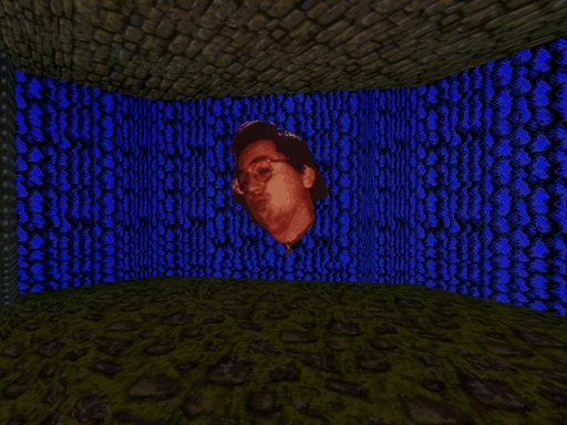
Ducklips lives!
On the whole, Saturn Quake is a pretty respectable effort. It has plenty of correctable problems, but given the timeline these guys had to basically make the game from scratch in their own engine on hardware with crippling limitations, I'm not criticizing anything. It seems like Lobotomy Software represents a classic story of big publishers bending a group of talented developers over a barrel, because having talent doesn't necessarily mean having leverage. They pulled off some remarkable feats while adhering to ridiculous schedules, and were left with the professional equivalent of a bloody asshole and a crinkled 10 dollar bill for their efforts. It's funny how little the industry has changed in the last 20 years.
Comments
3 comments in total.Post a comment
IP: 188.77.80.233
David Gámiz Jiménez
December 10, 2016 at 7:18 am (CST)Awesome research! And totally agree your conclusion. This history repeat this days... But at the end, the result is the important. And this guys have been the fucking masters in Sega saturn, only in 1 year to develop Duke3D and Quake... :D
IP: 71.82.5.174
Lubdar
May 14, 2015 at 11:35 pm (CST)Heh good read indeed!
IP: 24.173.233.250
Mick
May 6, 2015 at 12:20 am (CST)Ha! The last paragraph was worth the whole read.
Post a comment
Stream Tags
Projects
Everything
Personal
Analysis
Indie
Technology
AVALANCHE
R-Cube Engine
Modding
Game Design
Commercial
iPhone
Euphoria

Recent Comments
14147075 page hits since February 11, 2009.
Site design and contents (c) 2009 Rich Whitehouse. Except those contents which happen to be images or screenshots containing shit that is (c) someone/something else entirely. That shit isn't really mine. Fair use though! FAIR USE!
All works on this web site are the result of my own personal efforts, and are not in any way supported by any given company. You alone are responsible for any damages which you may incur as a result of this web site or files related to this web site.


